Technical Details
All condensate pots are designed in accordance with ASME VIII Div. 1 and produced in an ASME Coded workshop. All are CE* Marked to PED 2014/68/ EU for use with Group 2 Gases (non-hazardous) upon request.
ASME VIII U stamping and TR CU certification are available upon request & at extra cost.
Design temperature 100 °C.
** Other pressures, temperatures and materials available as special order. For these applications, please state pressure, temperature and material requirements.
Technical Specifications
- Standard size: Pipe size 3″ 4″ and larger size upon request
- Standard length: Pipe length 8″, 1 O”, 12″ and larger length as per volume and upon request.
- Working pressure: Up to 6000 psi [41 .34 M Pa]
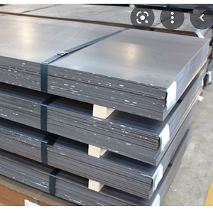
- Standard material of construction: SS316, SS316L, ASTM A 106Gr.B, ASTM A335 P11, P22, P92, ASTM A 182 F9/ F92
- Optional Sour Gas service valves are available, confirming to NACE Std. MR-01-75.
- Pipe Schedule: 40 80, 160, Seamless pipe.
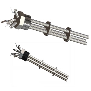
- Chamber as per ISA RP3.
- NPT as per ANSI B2.1 taper pipe thread½” furnished.
- Socket weld as per ANSI B16.11
- Butt-weld as per ANSI B16. 9
- All chambers are 100% factory tested prior to shipment
- Testing: Hydrostatic shell test is performed 1.3 times the working pressure.
Features
- CE”‘ marked to PED 2014/68/EU upon request.
- High/Low Pressure Rating options
- Available in 0.5 to 5.0L
- Range of exotic materials
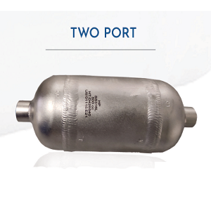
- Use as liquid or condensate traps, seal pots, vapour chambers and knockout pots.
- All connectors are furnished with plastic plugs
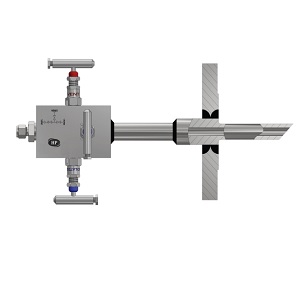
- Chambers are made from seamless pipe and weld caps. All pipe connections are 3000# /°6000# / 9000# half couplings mounted on 90 angle. Extra connections can be furnished upon customer request.
- All welding as per ASME SEC IX
- All butt-weld joints will be l 00% radiographed and fillet weld will be D.P. tested.
- All threads will be protected with dead plugs/plastic caps.
- ASME VIII U stamping and TR CU certification available on request.
Below listed are the related files that can be downloaded to you PC. All the files are in PDF format.